
Alternator faults are commonly associated with low charging output, unstable charging voltage, excessive AC ripple, abnormal bearing noise, belt vibration, worn carbon brushes, damaged slip rings, rectifier faults, and voltage-regulator failure.
Introduction
However, a charging-system fault does not automatically mean that the alternator itself is defective. Battery condition, wiring resistance, grounding, belt condition, pulley operation, and control-system faults can produce similar symptoms.
For repair shops and remanufacturing technicians, the correct procedure should therefore follow:
Vehicle diagnosis → Alternator identification → Controlled disassembly → Component inspection → Repair or replacement → Correct assembly → Bench testing → Vehicle verification
This procedure helps prevent secondary damage, unnecessary component replacement, and repeat repairs.
Important: Valeo alternators are available in different generations and configurations. Regulator design, pulley type, housing construction, component dimensions, torque values, and electrical specifications may vary by part number and vehicle application. Always use the service specification for the exact alternator being repaired. Do not apply generic torque or dimensional values across different models.
1. Identify the Alternator Before Disassembly
Before removing or dismantling the alternator, record the available identification information.
Check:
This information is important when selecting replacement components.
Do not assume that two visually similar Valeo alternators use interchangeable regulators, rectifier bridges, pulleys, brush holders, or bearings.
For B2B repair and parts operations, recording the complete alternator identification before disassembly can also reduce incorrect-part selection during reassembly.
- Valeo part number
- OE/OEM number
- Rated output/current
- Vehicle application
- Pulley type
- Electrical connector configuration
- Regulator type
- Housing configuration
2. Diagnose the Charging System Before Disassembly
A low or unstable charging voltage should be investigated before the alternator is dismantled.
2.1 Check the Battery
Verify:
A weak or damaged battery can affect charging-system test results.
- Battery state of charge
- Battery terminal condition
- Battery terminal tightness
- Battery condition where appropriate
2.2 Check the Charging Circuit
Inspect:
Excessive resistance in the positive or ground circuit can produce symptoms that resemble alternator failure.
- B+ cable
- Ground connection
- Alternator connector
- Fuse/fusible link where applicable
- Wiring condition
- Voltage drop under load
2.3 Check the Drive System
Inspect:
If the alternator uses an overrunning alternator pulley (OAP/freewheel pulley), check its operation separately.
- Serpentine belt condition
- Belt tension
- Belt alignment
- Automatic tensioner
- Alternator pulley
2.4 Check Electrical Output
Where appropriate, measure:
A voltage reading alone is not sufficient to confirm alternator health.
- Charging voltage
- Charging current
- AC ripple
- Charging response under electrical load
3. Tools and Safety Precautions
3.1 Recommended Tools
Depending on the alternator design, prepare:
- Socket and wrench set
- Torx/hex tools as required
- Torque wrench
- External circlip pliers
- Bearing puller/separator
- Suitable press and bearing support fixtures
- Pulley/OAP removal tools
- Multimeter with diode test function
- Battery/alternator tester
- Bench power supply where applicable
- Soldering equipment where applicable
- Electrical contact cleaner
- Cleaning brushes
- Suitable rotor and bearing inspection tools
3.2 Safety Precautions
Before removing the alternator:
During bench repair:
- Disconnect the battery negative terminal.
- Ensure the ignition is switched OFF.
- Prevent the B+ terminal from contacting ground.
- Allow the alternator to cool before handling.
- Mark or photograph electrical connections when necessary.
- Wear eye protection when removing retaining rings.
- Keep bearings and electrical components free from contamination.
- Support housings correctly when using a press.
- Keep loose wires away from rotating components.
- Never use uncontrolled force on the rotor shaft, housing, bearings, or electrical terminals.
4. Main Alternator Components
A typical alternator contains the following major components:
A single symptom may be caused by more than one component. For example, intermittent charging can result from a regulator fault, worn brushes, poor slip-ring contact, wiring resistance, or a combination of these conditions.
- Rotor — generates the rotating magnetic field
- Stator — contains the three-phase generating windings
- Rectifier bridge — converts generated AC into DC
- Voltage regulator — controls rotor field current
- Carbon brushes — transfer excitation current to the rotor
- Slip rings — provide electrical contact between the stationary brushes and rotating rotor
- Front and rear bearings
- Front and rear housings
- Drive pulley
- Cooling fan or integrated cooling arrangement, depending on design
5. Alternator Disassembly
5.1 Remove the Pulley
Use the correct removal tool for the specific pulley.
For an OAP/freewheel pulley, confirm the correct internal tool and locking method before applying torque.
Common mistakes
Prohibited operation
Do not clamp the rotor shaft directly in a vise.
Direct clamping can damage the shaft surface or introduce shaft deformation, potentially causing bearing, pulley, or alignment problems.
- Using an incorrect pulley tool
- Holding the rotor shaft directly in a vise
- Applying excessive torque
- Using an impact tool without confirming that the procedure is appropriate
- Reusing a damaged pulley
5.2 Separate the Housing
Remove the housing fasteners systematically.
Before separating the housings:
If the housing is difficult to separate, do not immediately use excessive prying force.
Common mistake
Using a screwdriver directly against a machined housing or bearing surface.
This can create:
Use designated separation points or suitable non-damaging tools.
- Photograph the original assembly.
- Record washer and spacer positions.
- Identify electrical connections.
- Confirm that no internal wire remains attached.
- Check for retaining rings or other securing components.
- Burrs
- Housing damage
- Bearing-seat damage
- Misalignment during reassembly
6. Rotor Inspection and Repair
Inspect the rotor for:
- Damaged field winding
- Burn marks
- Loose pole pieces
- Shaft damage
- Excessive shaft runout
- Slip ring wear
- Oil or coolant contamination
6.1 Slip Ring Inspection
Check for:
Minor surface discoloration does not automatically require rotor replacement.
Where machining is permitted, remove only the minimum material necessary.
Do not excessively machine the slip rings simply to obtain a smooth appearance.
The final diameter and surface condition must remain within the applicable manufacturer specification.
- Deep grooves
- Uneven wear
- Burning
- Excessive eccentricity
- Poor brush-contact areas
7. Carbon Brushes and Voltage Regulator
The carbon-brush and voltage-regulator assembly should be inspected as a system.
Check:
Common mistake
Replacing the voltage regulator without checking the slip rings.
If the slip rings are deeply worn or eccentric, a new regulator and brushes may also develop poor contact and fail prematurely.
Prohibited operation
Do not bend, twist, or excessively compress the carbon brushes during assembly.
If the brush-holder design requires the brushes to be temporarily retained during assembly, use the intended retaining method rather than forcing the brushes into position.
- Brush length
- Brush movement
- Brush spring pressure
- Brush-holder condition
- Slip-ring contact
- Regulator terminals
- Signs of overheating
- Electrical damage
8. Stator Inspection
The stator contains three-phase windings.
Inspect for:
Depending on the equipment available, perform:
The three phases should show consistent electrical characteristics within the manufacturer's specified tolerance.
Visual inspection alone cannot identify every winding fault.
- Burned insulation
- Open circuits
- Shorted windings
- Winding-to-core faults
- Loose connections
- Mechanical contact with the rotor
- Phase-to phase resistance comparison
- Continuity testing
- Insulation/ground-fault testing with suitable equipment
- AC output testing after assembly
9. Rectifier Bridge Inspection
The rectifier bridge converts three-phase AC from the stator into DC output.
A rectifier fault may result in:
A multimeter diode test can be used as an initial diagnostic method where appropriate.
However, the test result must be interpreted according to the rectifier's circuit configuration.
Common mistake
Testing the rectifier while other connected components influence the measurement and treating the result as definitive.
Where necessary, isolate the component before testing.
Prohibited operation
Do not apply uncontrolled external voltage directly to sensitive electronic regulator circuits.
Modern voltage regulators may contain semiconductor electronics that can be damaged by incorrect test procedures.
- Low charging output
- Excessive AC ripple
- Battery discharge
- Charging warning-light symptoms
- Abnormal charging behavior
10. Bearing Inspection and Replacement
Bearings should be inspected even when the original complaint appears to be electrical.
Check:
- Rotational smoothness
- Abnormal noise
- Radial or axial play
- Roughness
- Contamination
- Heat damage
10.1 Bearing Removal
When using a puller or press:
- Ensure the bearing is properly supported.
- Keep the force aligned with the bearing.
- Prevent force from passing through the rotor winding or other unsupported components.
10.2 Bearing Installation
The pressing force must be applied to the correct race.
When pressing a bearing onto a shaft: Apply force to the inner race.
When pressing a bearing into a housing: Apply force to the outer race.
Prohibited operation
Never transmit pressing or impact force through the wrong bearing race.
Incorrect force can cause internal bearing damage even when the bearing appears correctly installed.
11. Assembly Procedures
Before assembly:
- Clean the housing and mating surfaces.
- Inspect both bearing seats.
- Confirm all washers, spacers, insulators, and retaining components.
- Check rotor and stator condition.
- Confirm correct electrical terminal orientation.
- Inspect wiring routing.
- Verify that no wire can contact the rotor.
11.1 Rotor and Stator Alignment
During assembly, the rotor must remain correctly centered inside the stator.
After partial assembly, rotate the rotor manually.
There should be:
If interference is detected, do not simply tighten the housing further.
Possible causes include:
- No scraping, rubbing, binding, or abnormal rotational resistance.
- Incorrect bearing installation
- Incorrect spacer position
- Damaged housing
- Rotor shaft runout
- Incorrect component positioning
12. Fastener Tightening
Use a calibrated torque wrench where torque specifications are available.
Do not rely on:
Over-tightening may damage:
Under-tightening may result in:
Use the exact torque specification for the alternator's part number or applicable service documentation.
- Hand-tightening
- Previous technician settings
- Impact-tool settings
- Generic alternator torque values
- Aluminum housing threads
- Small fasteners
- Electrical terminals
- Bearing seats
- Housing movement
- Vibration
- Electrical connection resistance
- Fastener loosening
13. Pulley Installation
Before installation, confirm:
An OAP/freewheel pulley is not equivalent to a conventional fixed pulley.
Common mistake
Installing a visually similar pulley without confirming its specification or rotational behavior.
Potential consequences include:
- Correct pulley specification
- Correct installation direction
- Shaft compatibility
- Locking method
- Freewheel operation where applicable
- Belt vibration
- Abnormal noise
- Poor belt-tension behavior
- Premature pulley failure
- Unstable operation during load changes
14. Common Errors That Cause Repeat Repairs
14.1 Replacing Only the Apparently Failed Component
Example:
Regulator replaced → alternator reinstalled → charging fault returns.
The underlying problem may be:
Correct approach: Inspect the complete excitation and charging circuit.
- Worn slip rings
- Poor brush contact
- Damaged rectifier
- Ground resistance
- Rotor winding fault
14.2 Ignoring Bearings During Electrical Repair
An alternator can pass an electrical test while having a mechanically defective bearing.
Always evaluate:
- Noise
- Play
- Smoothness
- Contamination
- Rotational resistance
14.3 Excessive Slip Ring Machining
Aggressive grinding can:
Remove only the minimum material necessary and remain within the applicable specification.
- Reduce slip ring diameter
- Create eccentricity
- Affect brush contact
- Reduce component service life
14.4 Incorrect Bearing Pressing
A bearing can appear properly seated while already suffering internal damage.
Always control:
- Support location
- Pressing direction
- Applied force
- Final seating position
14.5 Incorrect Washer or Spacer Position
Washers and spacers may look similar but have different functions.
Incorrect installation can affect:
Photograph and document the original assembly before disassembly.
- Rotor position
- Bearing preload
- Electrical insulation
- Pulley alignment
- Housing clearance
14.6 Testing Only Charging Voltage
A normal voltage reading does not prove that the complete charging system is functioning correctly.
Where appropriate, evaluate:
- Charging voltage
- Charging current
- AC ripple
- Voltage drop
- Load response
- Mechanical noise
- Belt and pulley operation
16. Bench Testing After Repair
Before installing the repaired alternator, perform a controlled bench inspection/test where suitable equipment is available.
Check:
Mechanical
Electrical
Use the test limits specified for the exact alternator model.
Do not use a generic charging-voltage or resistance value as a universal acceptance criterion.
- Rotor rotates smoothly
- No rotor-to stator contact
- Bearings operate quietly
- Pulley operates correctly
- No loose components
- Rotor/field circuit
- Stator windings
- Rectifier bridge
- Regulator/brush assembly
- Output performance
- AC ripple
17. Vehicle Installation and Final Verification
After installation:
Before Starting
After Starting
Under Electrical Load
Apply appropriate electrical loads, such as:
Monitor charging-system response.
Where professional diagnostic equipment is available, verify:
If the charging system remains abnormal after alternator repair, recheck the battery, cables, grounds, belt drive, tensioner, and vehicle control system before removing the alternator again.
- Check: Battery terminals
- B+ connection
- Ground connection
- Alternator connector
- Belt routing
- Belt tension
- Pulley alignment
- Check: Charging warning lamp
- Charging voltage
- Alternator noise
- Belt vibration
- Pulley behavior
- Headlamps
- Blower motor
- Rear defogger
- Other major electrical consumers
- Charging voltage
- Charging current
- AC ripple
- Voltage drop
- Load response
18. Final Repair Checklist
Before returning the alternator to service, confirm:
- Correct alternator part number/application identified
- Battery and charging-system fault diagnosed before disassembly
- Rotor rotates smoothly
- No rotor-to stator interference
- Rotor winding inspected
- Slip rings inspected and remain within applicable limits
- Carbon brushes move freely
- Brush contact is satisfactory
- Voltage regulator inspected/tested
- Stator windings inspected
- Rectifier bridge tested
- Bearings inspected or replaced as required
- Washers and spacers installed in the correct positions
- Electrical insulation components correctly installed
- Housing fasteners tightened to model-specific specifications
- Correct pulley installed
- Pulley direction/function verified
- B+ and ground connections secure
- Bench test completed where applicable
- Vehicle charging performance verified under load
- No abnormal noise or belt vibration present
Conclusion
Successful Valeo alternator repair depends on more than replacing the component associated with the initial fault. The alternator is an integrated electromechanical system in which rotor excitation, carbon-brush contact, slip rings, stator windings, rectification, voltage regulation, bearings, pulley operation, and mechanical alignment all affect final performance.
The most reliable repair process is:
Diagnose first → identify the exact alternator → disassemble correctly → inspect every relevant component → repair or replace according to specification → assemble with controlled force → bench test → verify the complete vehicle charging system.
The most common sources of repeat repair are incorrect bearing installation, excessive slip-ring machining, poor brush/slip-ring contact, incorrect pulley installation, misplaced spacers or insulating components, improper fastener tightening, and failure to diagnose the vehicle's charging circuit before alternator removal.
Because Valeo alternator configurations vary by application, model-specific service information should always take priority over generic repair procedures, dimensions, torque values, and electrical test limits.
Related parts
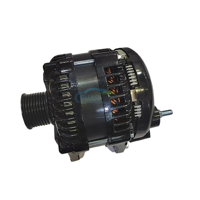
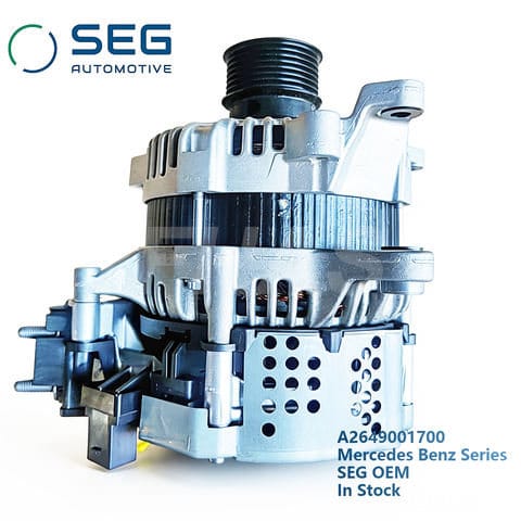
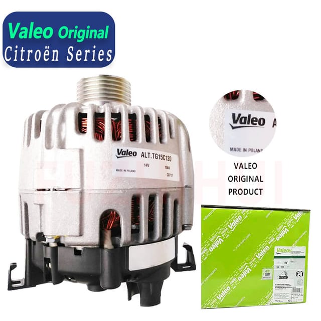
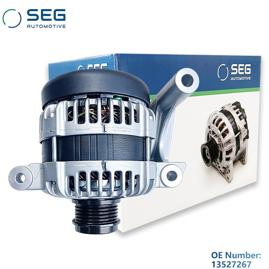
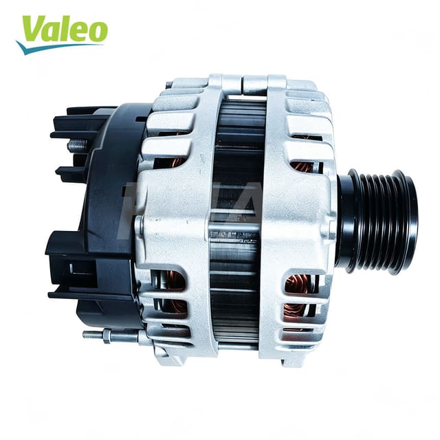
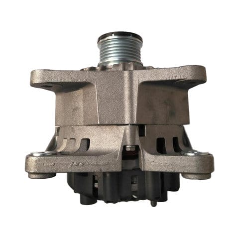
Units from our range. Send an OE number and we will check fitment before quoting.
Have a part number to price?
Send it over with the quantity and destination. You will get a fitment check, a unit price and a freight cost — usually the same business day.